News Letter
Sign Up & get 33% off your first order
Enter your preferred name & e-mail to subscribe


Pressure reducing valves (PRV) are designed to reduce, regulate, protect and automatically maintain a stable and consistent reduced pre-set outlet (downstream) pressure regardless of pressure differentials, inlet pressure changes or down stream flow demand which in turn will reduce and minimise flow noises and water consumption.
| Efficient Water Consumption | |||
| Water Pressure |
Water Consumption per person a day |
Water consumption per year per 4 person house |
Water consumption percentage |
| 6.0 bar | 140 Litres | 200 m³ | 100% |
| 4.0 bar | 113 Litres | 162 m³ | 81% |
| 3.0 bar | 99 Litres | 142 m³ | 71% |
The reduced outlet downstream pressure is displayed by a pressure gauge mounted on the top of the direct acting pressure reducing valve and depending on the manufacturers pressure reducing ranges selected will offer adjustable pressure reductions from 25 bar down to ranges of either 1 to 6 bar, 4 to 10 bar or 8 to 13 bar according to the internal spring compression ranges.
For example a strong spring will compress with better accuracy and repeatability better under higher loading or higher pressures whereas a softer spring would compress with better accuracy and repeatability under lower loading or lower pressure ranges. As the pressure range adjustment range relies on mainly the spring tension it is simple way of offering direct accurate pressure reducing control and special pressure ranges are easily obtained by installing a suitable spring. The spring compression has to allow room to compress or expand further within this set range otherwise the pressure reducing valve will not work accurately. Manufacturers spend a lot of time testing different spring lengths and cost testing different combinations of spring thickness's, hardnesses etc to find the best most reliable, accurate, repeatable linear compression to force ratio of spring or combination of springs.
For example if you consider a car spring suspension the springs are designed to compress under the loads / weight expected in the car, if you over load the car the springs will compress to far and be unable to compress more to absorb bumps, on the other side of the scale if you fitted the car springs to a bicycle the load would be insufficient to compress the springs at all so again the bumps could not be absorbed.
Additionally the springs used need to compress in direct proportion to force and this accuracy needs to be repeatable to high levels of accuracy, so don't be fooled by cheap alternatives as these are probably unlikely to perform well in the short or long term.
The direct acting pressure reducing valve is designed for smaller applications up to 2" thread or Flange where the pressure balanced piston is direct connected to the spring and adjustment screw. In this way the pressure reducing valves does not reply of any pressure difference between inlet and outlet which is commonly available on larger flanged pressure reducing valves from DN50 upwards, thus making it idea for low flow or closed circuit pressure balanced systems.
There are also additional benefits can be obtained by the materials of construction, for example if a direct acting pressure reducing valves is all 316 Stainless Steel body and internal parts this will offer strong wear and corrosion resistance and will probably be suitable for most applications air, gas and fluid media. However stainless steel is typically a similar cost to brass and bronze due to recent material price increases, so in essence it is prudent for pressure reducing valve manufacturers to produce only 316 stainless steel pressure reducing valves thus utilising the cost advantages of a single manufacturing and production system, rather than producing brass or bronze pressure reducing valves.
Pressure Adjusting Ranges:1 to 6 Bar, 4 to 10 Bar or 8 to 13 Bar.
Pressure needed from fully closed gate to fully opened gate: 1.5 Bar
Applied Temperature:-15°C to +100°C
Maximum Applied Pressure: 25 Bar
 |
|
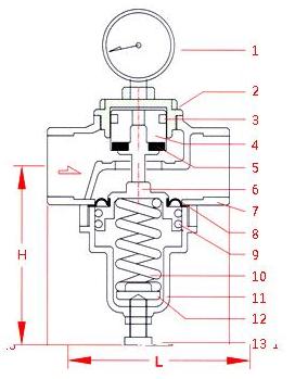
1. Pressure Gauge - Stainless steel 2. Valve cover - 316 Stainless steel 3. O Ring - FKM 4. Piston - 316 Stainless steel 5. Seals - FKM 6 Shaft - 316 Stainless steel 7. Valve body - 316 Stainless steel 8. Diaphragm - FKM 9. O Ring - FKM 10. Spring - Steel 11. Valve cover - 316 Stainless steel 12. Washer - Brass 13. Stem - 304 Stainless steel
|
 |
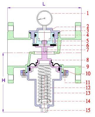
1. Pressure Gauge - Stainless steel 2. Valve cover - 316 Stainless steel 3. O Ring - FKM 4. U Ring - FKM 5. Piston - 316 Stainless steel 6. Seals - FKM 7. Shaft - 316 Stainless steel 8. Diaphragm - FKM 9. Valve Body - 316 Stainless steel 10. UH Ring- FKM 11. Bolt - 304 Stainless steel 12. Spring - steel 13. Valve Cover - 316 Stainless steel 14. Washer - Brass 15. Stem - - 304 Stainless steel |
|
|
Installing a direct acting pressure reducing valve directly in the sub-pipe can reduce fluid pressure inside the pipe. Installing a filter in the inlet of pressure reducing valve can prevent problems caused by impurities and lime scale. Installing pressure relief valve downstream pressure reducing valve can protect the system from over pressure and water hammer. |
|
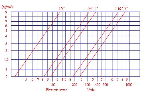
To make a direct acting pressure reducing valve fully open you will need to know the adjustable pressure range, inlet and outlet pressures, below are the calculations to work out the pressures required for valve to be in fully open position. A. Pressure drop needed for fully-opened valve 0.25 x pressure adjustment range B. Adjustable Pressure Range Maximum – Minimum C. Setting Pressure Of outlet D. Pressure of fully open outlet is C - A Example:Pressure drop needed for fully-opened valve gate for adjusting pressure range 3~9 Bar of direct acting pressure reducing valve.If the setting pressure of outlet is 6 Bar, pressure of fully-opened valve gate will be P=6-1.5=4.5 Bar (Outlet pressure should go down under 4.5 Bar to make valve gate fully open) |
|

A catalouge of articles covering all aspects of solenoid valves
Enter your preferred name & e-mail to subscribe